Inhaltsverzeichnis
Working with a pointing device
Introduction
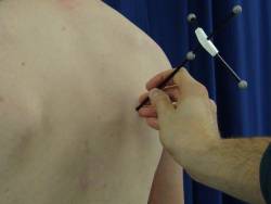
 A typical workflow, based on marker-clusters, includes the usage of a so called „pointer“ to define anatomical prominences of bony structures.
The pointer needs at minimum two markers, but typically four markers are used for better „autolabeling“ function.
If you are a Vicon Nexus user and you are alone with the subject you want to measure it can be handy to use the smartphone and the Vicon Control App for starting and stopping the measurements during positioning the pointer.
Why using a pointer instead of a marker?
- A marker placed on an anatomical landmark can move a lot (e.g. skin motion artefacts). Only pointing such a position in an static trial makes it clear that the defined position is valid only for this.
- Anatomical landmarks can be obscured by fat (e.g. the Pelvis ASIS markers for overweight subjects)
- Anatomical landmarks can be obscured from the cameras (e.g. some medial landmarks) or can be too close together (e.g. on the foot), which makes its tracking challenging
- To attach markers, the subject must expose that part of the body, which can be uncomfortable (e.g. Landmarks at the sternum for women)
Modelling with tip positions
To determine the position of the „tip“ of the pointer from the markers of the pointer, the kinematic model has to implement this feature, e.g.:
 <Point name="P"
           includes="locator">LOCATOR3+normalize(LOCATOR1-LOCATOR3)*LocatorLength
 </Point>
The formula of the code fragment above includes the labels „LOCATOR1“ and „LOCATOR3“. These are the names of the markers, as defined in the „input-labelset“:
<?xml version="1.0" encoding="UTF-8"?>
<LabelSet name="Markers">
  <Labels name="Markers" baseFile="true">
     <Label name="LOCATOR1"/>
     <Label name="LOCATOR2"/>
     <Label name="LOCATOR3"/>
     <Label name="LOCATOR4"/>
     ...
The kinematic model you can find in the „Models“ subfolder of your project. If there are more than one model, you have to check, which one is used as default. This is defined in the „cmlproject.xml“, which you can find in the „Jobs“ subfolder of your project. The used kinematic model you can find as value of the attribute „defaultmodel“ of the xml-element <CalcMLProcessConfig>, e.g.:
<?xml version="1.0" encoding="iso-8859-1" ?>
<CalcMLProcessConfig name="UEGeneral2 HUX + Cluster"
                     version="1.0"
                     defaultmodel="UEGeneral2+Cluster_without-SHO-markers.xml"
                     defaultmarkerset="Input.xml"
                     defaultconstants="constants.properties"
                     defaultview="StickFigure.xml"
                     useEventsFromSessionMetaDataFile="false">
...
In this code fragment above you can also see which is the name of the default input-labelset. The attribute name is called „defaultmarkerset“. The referenced labelset files you can find in the subfolder „Labelset“ in you project.
The formula to define the tip of the pointer also includes a label with the name „LocatorLength“. This points to a constant, which is defined in the „constants.properties“ file in the subfolder „Constants“ of your project, e.g.:
MarkerDiameter=9.5
FuncionalTrialAbdukROM=45.0
RabShoulderOffset=0.17
LocatorLength=119,5
To define an anatomical coordinate system of a bony segment, three points have to be pointed. Typically each poining is done in a separate „static trial“. To collect the data of these trials, each of the trials has to be recognized by the model. It has to recognized which point is pointed and it has to be formulated in the model how to determine an anatomical coordinate system based on these points and the cluster coordinate system.
Eclipse entries
Using a Vicon motion capture system, the needed information to recognize the trial, can be saved as a property in the so called „Eclipse“ functionality. In newer Eclipse version used as default in the Vicon Nexus system has the following properties as default, which can easy be used. Typically the attributes with the names
 ACTIVITY
 SIDE
 TYPE
The Attribute „ACTIVITY“ can be used to define, which bony position is pointed, if the position is side dependend the attribute „SIDE“ can be used additionally and the attribute „TYPE“ can be set to „static“ to say that it is a trial without motion.
How to recoginize a trial based on these attributes is defined in the so called „job configuation“. It is the file „cmlproject.xml“ in the subfolder „Jobs“ in your project.
Have a look at the following code fragment:
  <CalcGroups sequence="... static_calibrate_T8 static_calibrate_right_SC static_calibrate_right_AC ...">

     <!-- calibration by locator -->

     <!-- thorax -->
     <CalcGroup name="static_calibrate_T8">
        <identification>
          <entry key="TYPE">Static_Cal|Static</entry>
          <entry key="ACTIVITY">Thorax T8</entry>
          <entry key="SIDE">Both</entry>
        </identification>
        <process>
            <entry key="POINTS">true</entry>
            <entry key="NOEVENTS">true</entry>
        </process>
        <output labelset="empty.xml" dir="">
            <entry key="integerDigits">10</entry>
            <entry key="fractionDigits">5</entry>
        </output>
        <!--output labelset="Output_calibrate.xml"
                handlerclass="de.orat.motionDataConverter.MotionDataOutputHandler">
        </output-->
     </CalcGroup>
The element <CalcGroup> defines a group of trials. In the case of pointing, typically such a group should include only one trial. The entries in the <identification>-element define how a trial is recognized. Each <entry>-element defines the values an attribute with a given name must set to, so that the trial is recognized as a member of this group of trials.
The value is given as an regular expression.
The allocation to a trial group is one part. In the case of a pointing trial the calculation depends on it. Thatś why as an additional step a „switch“ must added. This is also defined in the „job configuration“, e.g.:
 <Switches used="locator static_calibrate_right_GH static_calibrate_left_GH static_calibrate_T8 ...">

      <switch name="locator">
          <entry key="TRIALCATEGORY">static_calibrate_right_GH|static_calibrate_left_GH|static_calibrate_T8|...</entry>
      </switch>
      ...
      <switch name="static_calibrate_T8">
          <entry key="TRIALCATEGORY">static_calibrate_T8</entry>
      </switch>
The switch with the name „static_calibrate_T8“, the same name as for the corresponding group, is simply defined, if the trial is part of that trial group.
This switch can be used in the kinematic model:
...
<CoordinateSystem name="Thorax_Cluster"
              Position="THRX1"
              FirstAxis="THRX2-THRX1"
              DefiningVector="THRX3-THRX1"
              orientation="xyz"/>
    <Point name="T8"
              coordinateSystem="Thorax_Cluster"
              calibrateIncludes="static_calibrate_T8"
              excludes="static_calibrate_left_GH,static_calibrate_right_GH">P</Point>
    ...
The point „T8“ is defined by the point „P“ of the locator in the trial for which the switch „static_calibrate_T8“ is set. For all other trials the point „T8“ is calculated by the technical coordinate system „Thorax_Cluster“ based on relative coordinates saved by the static calibration trial „static_calibrate_T8“, the trial in which the point „T8“ is pointed by the pointer.
